Choosing root ports
Once the root bridge is chosen, a Root Port must be chosen for each switch, which is not the root bridge. The root port always points to the root bridge.
STP assigns locally in the switch a value called path cost to each of the switch ports according to their bandwidth:
| Bandwidth | Path Cost |
| 10 Mbps | 100 |
| 100 Mbps | 19 |
| 1 Gbps | 4 |
| 10 Gbps | 2 |
The root port should be the best path to the root bridge defined by the lowest cumulative cost of all the interfaces or links that a switch uses on its way to the root bridge. This value is called root path cost and is widespread in BPDUs. Do not confuse path cost with root path cost because they are different terms; path cost is only the value of a port in the switch, and root path cost is the sum of all the path costs of the ports or links of the different switches to reach the root bridge.
Let’s look at the following topology to explain the allocation of the root ports taking SW1 as a reference as a root bridge:
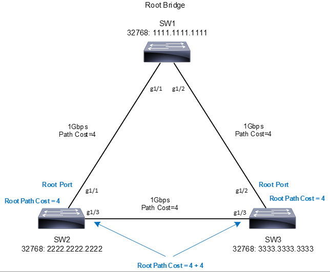
The SW2 perspective is as follows:
- SW2 has two viable paths to reach the root bridge (SW1).
- The g1/1 interface has a Root path cost equal to 4 because the root bridge has it directly connected through a 1Gbps link.
- The g1/3 interface has a Root Path Cost of 8 because to reach the root bridge it is necessary to go through SW3, in total two 1Gbps links are used with a cost of 4 per link.
- STP chooses the g1/1 interface as the root port because the Root Path Cost is lower.
The SW3 perspective is similar to that of SW2:
- SW3 has two viable paths to reach the root bridge (SW1).
- The g1/2 interface has a Root path cost equal to 4 because the root bridge has it directly connected through a 1Gbps link.
- The g1/3 interface has a Root Path Cost of 8 because to reach the root bridge, it is necessary to go through SW2, in total two 1Gbps links are used with a cost of 4 per link.
- STP chooses the g1/2 interface as the root port because the Root Path Cost is lower.
NOTE: The root bridge sends BPDUs with a root path cost equal to zero because its ports are directly on the root bridge. When the nearest neighboring switch receives the BPDU, it adds the path cost value of the port where it received the BDPU and updates the Root Path Cost field before forwarding the BPDU over its other ports connected to other switches.
Selecting Designated Ports
First, all ports on the root bridge are designated. STP identifies a designated port for each network segment, collision domain or link to send traffic to and from that segment.
Designated ports are the non-root ports that connect to other switches or end devices on the network. But if there is a link between two switches that have an alternate path to the root bridge. In this scenario, both ports cannot be designated; if both ports were designated ports, we would have a layer 2 loop; here is where STP blocks specific ports.
We continue with the premise that each collision domain must choose a designated port. According to the above topology, we see that SW2 and SW3 have a link (collision domain) through ports g1/3. Only one of the ports can be the designated port in this link, and the choice is made under certain criteria.
The designated ports are chosen according to:
- Lowest cost to the root bridge (Root Path Cost)
- Lowest bridge ID of the switch sent in the BPDU
- The lowest port ID is sent in the BPDU. It is used when you have two links or more than one switch to the root bridge and is set to the switch closest to the root bridge (the one sending the BPDU).
Note: The port ID is a value from 0 to 255 and can modify it within the port by specifying the vlan. The default value is 128.
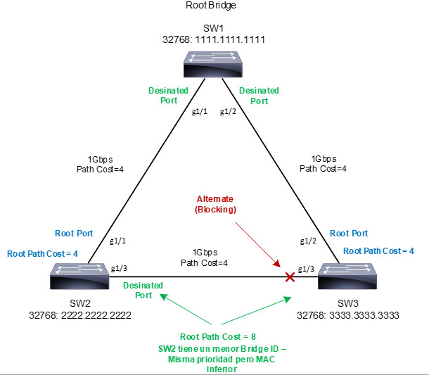
In our example diagram, we see that the g1/3 ports of SW2 and SW3 have the same Root Path Cost, therefore they use the second election criteria for a designated port. SW2 gets the designated port because the bridge ID is less than that of SW3.
Since it is known that SW3’s g1/3 port cannot be the designated port, nor root port, any port that is not chosen for any of the above options enters the Blocking state, and the loops are eliminated. Let’s look at the result of the diagram:
Port States
All ports participating in STP must pass through several states. A port starts in a disabled state, moving through several passive states and at the end moves to an active state where it is allowed to forward traffic. The STP port states are as follows:
- Disabled: Port not operational. Does not send data/BPDU. Ports that are administratively shut down by a network administrator or by a fault condition such as err-disable, etc.
- Blocking: After a port is initialized, it starts in the Blocking state so that no loops are formed. In a Blocking state, a port cannot receive or transmit data and cannot add MAC addresses to its address table. Instead, a port can receive only BPDUs so that the switch can listen to other neighboring switches. In addition, ports that are put into standby mode to remove a loop enter the Blocking state. In short, it is the port that only receives BPDUs from its neighbor; these BPDUs are useful if the port needs to change to Listening, Learning and Forwarding states.
- Listening (LIS): A port moves from Blocking to Listening if the switch considers that the port can be selected as a root port or designated port. Here the port still cannot send or receive data frames. However, the port can receive and send BPDUs so that it can actively participate in the Spanning Tree topology process. If the port is a candidate for being a root or designated port, it will move to the next Learning state.
- Learning (LRN): The port can move to the learning state after a period of time called forward delay in the listening state. The port still sends and receives BPDUs as before. In addition, the switch can now learn new MAC addresses to add to its address table. This gives the port an extra period of silent participation and allows the switch to collect some address information. However, the port still cannot send any data frames. It sends and receives BPDUs and learns MAC addresses.
- Forwarding (FWD): The port can move to the forwarding state after another delay period in the learning state. The port is now a fully functional port within the spanning-tree topology. It sends and receives BPDUs, learns MAC addresses, can send and receive data. The forwarding state on a switch is only allowed if no redundant links are detected that could cause Layer 2 loops and if the port has the best path to the root bridge as a root port or designated port.
STP Timers
STP uses three timers to ensure that the network converges properly before a loop can form:
- Hello timer: This is the time interval between configuration BPDUs sent by the root bridge. The hello timer value configured at the root bridge determines the time for all switches other than the root bridge, these switches simply retransmit configuration BPDUs as they are received from the root bridge. However, all switches have a locally configured hello timer that is used to synchronize TCN BPDUs as they are retransmitted. The IEEE 802.1D standard specifies this value as 2 seconds by default.
- Forward Delay Timer: Time interval that a switch port spends in the Listening and Learning states. The default value is 15 seconds
- Max (Maximum) Age timer:Time interval that a switch stores a BPDU before discarding it. Each switch port stores a copy of the “best” BPDU it has heard when running STP. If the switch port loses contact with the source of the BPDU (no more BPDUs are received), the switch assumes that a topology change must have occurred after the maximum aging time has elapsed, and therefore the BPDU is expired. The default value of the Max Age timer is 20 seconds.
The STP timers can be modified from the CLI. However, the modification must be thoroughly analyzed. If the timers need to be adjusted, the changes should be made only on the root bridge; these changes will be announced on the BPDUs to the other switches.
Topology Changes
Once the STP topology is defined and a change is generated, STP announces these changes through a BPDU TCN (Topology Change Notification).
An STP topology change occurs when a switch moves a port to the forwarding state or when a forwarding or learning state port is sent to the blocking state.
The process of a topology change is as follows:
- The switch that detects the change sends a special message known as a TCN (Topology Change Notification).
- TCNs are sent through all the root ports of the switches until they reach the root bridge. These TCN BPDUs must be acknowledged (TCA Topology Change Acknowledgment).
- The root bridge sends the BPDUs with the TC (Topology Change) flag set. These BPDUs will continue to be sent by Forwarding Delay (15 sec) + Max Age (20 sec). In other words, BPDUs will be sent every 2 seconds for 35 seconds with the TC flag.
- All switches (including the root bridge) that receive BPDUs with the TC flag active reduce the time of their MAC table for the affected VLAN to the Forwarding Delay time (15 sec). In other words, the MAC table reduces its aging time from 5 minutes to 15 seconds for the affected vlan. All MACs that do not send anything in 15 seconds are deleted, and then the root bridge sends the BPDUs again without the TC flag, and the mac table is reset to 5 minutes.
We have already seen what Spanning-Tree is, port roles/states, timers and how topology changes occur. Now let’s talk about Spanning-tree versions in cisco switches and their configuration and validation.